Modeling with LeoCAD

Ivonne Wierink, 123RF.com

Ivonne Wierink, 123RF.com

Building Blocks

Putting together realistic models on a computer screen can be useful and fun. LeoCAD
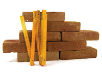
Older generations may still remember playing with wooden blocks or using sand to build castles and roads. Others may have played with model train sets. But, building things came into its own with Lego. Lego pieces are made from colorful plastic and fit together with a grid system of knobs and holes.

Lego has been around since 1947 and is manufactured by the Danish toy company Lego Group [2]. Competitors have used the idea to create a smaller market segment but their products don't always work with the original.

Originally intended for children, Lego is now used by young and old alike. Different sets have been specially designed for specific age groups. The older the target group, the smaller and more versatile the individual bricks. (See the "Legos and Electronics" box for more information.) The biggest advantage here is that you can always combine all of the bricks from one product line together. This means that you can bring your own ideas to building with Legos and develop your skill as a builder.

Legos and Electronics

Since about 1996, electronic components have been included in some Lego series. In the beginning, these were called Lego Technical Computer Control. This product line moved into the Robotics category around the year 2000 and is now sold as Lego Mindstorms.

A constant theme has been to have a basis for programming and controlling components such as motors, lights, and pneumatic elements. Originally dubbed Robotic Command Explorer (RCX), it has been sold under the name of Lego Mindstorms NXT since 2006. NXT is programmable in Python with the NXT-Python [3] software package.

Since 2013, the control brick product line has been called Mindstorms Evolution 3 (EV3), and it is still compatible with NXT. Both NXT and EV3 use the same hardware base and both have an ARM processor.

Linux software is packaged into these products and can be used with Debian GNU/Linux by changing the memory card [9]. A parallel product development by the name of ev3dev [4] lets you incorporate prepared images for Linux, Mac OS X, and Windows.

Fond Memories

If you are waxing nostalgic for a beloved set of building blocks from your childhood, you may have already searched through your attic or storage room. Even if you are lucky enough to locate them, however, you may find that there are not enough pieces to build the project you have in mind.

Just as in the building trades, replacement parts can be expensive, especially because they may become rare after a while. Pick a Brick [5] is a good source for replacement parts. This is a Lego service that lets you order individual parts in almost every color and amount, even for sets that may no longer be sold. BrickLink [6] is also a good source; it is an international dealer platform for bricks and models.

Clicking a Model Together

For those of you who are considering drawing up construction plans, it is a good idea to take a look at the software packages that might help you with the process. LeoCAD is an open source graphical program that can be used to click together a model you have designed on a display screen. LeoCAD is easy on the budget, and it also saves the time and frustration of waiting for real-life bricks to be delivered.

LeoCAD also offers the advantage that you can work with an unlimited number of virtual building bricks. However, the program requires some patience and skill from a user so that the bricks can be placed in the correct position for anchoring.

The starting point is placing the model inside a three-dimensional space. LeoCAD has all the tools you need to rotate the model on each axis in the space you have chosen. It also allows you to zoom in, create a background image and lighting effects, and prepare the model data for further processing by rendering programs such as POV-Ray, WaveFront, and 3D Studio [7].

In addition to LeoCAD, you will need the LDraw library [8]. At first glance, this library appears merely to add considerably to the bricks available in LeoCAD. However, LDraw also designates one of the open standards for Lego CAD programs applicable to the creation of models together with their assembly instructions and animations. Unfortunately, this software is not available with an open source license.

You will find ready-made packages in the repositories for Debian GNU/Linux and Ubuntu. LDraw is located in the Idraw-parts package [9] in the non-free area or multiverse. These can be easily installed using the package manager on your system. You can start LeoCAD via the Unix command of the same name.

What Is LeoCAD?

LeoCAD is a GUI program with three operating components. These include: (1) a bar that sits at the top for icons and the menu; (2) a centrally located model image with a coordinates system in the form of a grid; and (3) a selection area containing a list, a rotatable preview of the bricks together with a search box, and three color palettes on the right.

The palette includes both standard and mixed colors as well as a transparency option. The three color palettes are labeled as "solid colors" (top), "special colors" (bottom), and "translucent colors" (in the middle). There are no restrictions for using any of these colors for any of the bricks.

The program offers access to most of the actions via menu entries and via icons. Below, I use a small Tux model to introduce the capabilities step-by-step which LeoCAD offers. The Tux is shown as a mascot because this is how it was presented at the Linux Days 2015 [10].

The center piece of your work consists of the model image sitting in the middle of the program window. At the beginning, this will show an empty, transparent surface with knobs. The dimensions of the grid will automatically adapt to the size of the model.

The first step in constructing the penguin (Figure 1) is to create the characteristic yellow feet. To do this, go to the selection area for the color palette labeled "solid colors" and select the corresponding square. Then, select a 2x3 plate from the "plate" category and add this to your model via Ins. As an alternative, you can use the menu entry Piece | Insert or the icon with the gray building block that is to the left of the lightbulb.

Figure 1: First phase of construction.

You will now need three white bricks for the belly of the Tux. Two of the bricks should be 2x2 in size and tapered. The third brick should be a plate that fits in between. Then, select white from the color palette and then choose brick "Slope Brick 45 2x2 inverted."

To retrieve this brick, you will need to enter "inverted" in the search box of the selection area as a filter. Only entries that include the text " inverted" will appear. The search is case-insensitive. Empty spaces are significant. Apparently, LeoCAD processes an entry as a single character string.

After you have added this brick to the model image via Ins, you can use the blue double arrow to rotate the brick around the vertical axis and into position. This is done by clicking with the left mouse button on the blue double arrow and holding the mouse button until the brick is rotated 90 degrees to the right and it fits into the grid. Then, use the left mouse button to click on the vertical blue arrow and drag the block downwards until it sits flush on the yellow plate. The process is similar for the "Plate 2x2" brick and the "Slope Brick 45 2x2."

The back and the two wings of the Tux are black. Thus, you need a "Brick 1x2," a"Plate 2x1," and two "Slope Brick 33 3x1" for the two wings. To position all of these bricks correctly, you should rotate the model by 90 degrees clockwise. This is done by clicking on the icon with the circle and the three arrows. A circle with four squares will appear. These four squares are used to effect rotation around the appropriate axis. Hold down the left mouse button to execute the rotation (Figure 2). This lets you view the model from all sides to find the ideal position for adding these bricks.

Figure 2: Second phase of construction.

The final step here is to finish the head of the Tux. The head consists of three small 2x2 plates – two black and one yellow – a black 1x2 brick, a small black 1x2 plate, and two white 1x1 bricks together with eyes made from "Brick 1x1 with Headlight." The eyes consist of two round plates in black – "Plate 1x1 round" – that you should put on the front of the two white bricks. You can see the results in Figure 3.

Figure 3: Third construction phase.

After finishing, you should save the model as a file or export it in another format via (File | Export ). Options for export formats include Renderer, HTML/PNG, the comma-separated values format CSV, and a combination for the e-commerce platform Brick Link [6].

Tools and Aids

LeoCAD also has a small number of very useful tools and aids that can make the construction process easier. The menu entry View | Viewpoints can be used to change the angle of vision and perspective of your model. Views are available for the front, back, sides, top, and underneath.

When used along with the guidelines and the grid, these views are helpful for orienting an object in a multi-dimensional space. These views also simplify construction of the model. By using the menu entry View | Projection , you also can switch between a perspective in which the planes are displayed and a uniform perpendicular perspective. Your choice depends on which is more helpful for you.

Three icons are used to control the movement of the model pieces. The icon showing a grid with lock blocks movement and prevents the accidental shifting of the bricks. The grid with red dot icon lets you snap a brick in place at the intersection points on the axis and move a brick along segments of an axis that are equal in size to half the length of the brick. Using the angle with magnet icon lets you restrict angular steps to one rotation. Unfortunately, it is not possible to determine from the icons which state is currently active.

You can move a selected brick very precisely along its X,Y, and Z axes, by using the icon showing a red dot with arrows, and the three entry fields next to it. For this activity, movement by one brick length approximately corresponds to the value of 0.8 on an axis.

To move an individual brick or a group of bricks along a particular axis, you should use the icon with the four arrows. The three colored arrows that were presented in the discussion of the first construction phase will appear on the brick. The next icon over – the arrow with circle – lets you rotate around one axis.

You can manually move the entire image with the help of the icons. Here, it is good to have a sensitive touch, because the control element is set very precisely. Zoom lets you get a closer look at the model. If you only want to enlarge a rectangular-shaped subarea, use the icon with the magnifying glass set into a square.

If you open up a rectangle with the mouse, then all of the bricks found inside that rectangle will be highlighted. You can add the highlighted sub area to a named group via Piece | Group or by using Ctrl+G. You can then use this new group again in the modeling. In other words, you can move, rotate, copy, and delete it.

If you want to remove a brick, select the eraser icon and then click with the left mouse button on the brick you want to remove from the model. The color bucket is used to change the color of a brick. A left click on the brick coats it with the color that was earlier specified via the color palette.

Nice Features

LeoCAD has a few more highlights that should be mentioned here. These include the capability to put together your own figures, the list of bad construction parts, and the creation of construction instructions and lighting effects.

Your model comes alive only if the entire background looks realistic. Making this happen requires figures that you can put together individually with the help of the figure configurator. This tool is found in the menu under Piece | Minifig Wizard .

You can outfit the figure with all kinds of identifying features including a hat, hair, face, equipment, body, pants, shoes, etc., and then add the figure to the model. Figure 4 shows a small wild warrior wearing roller skates and holding a sword.

Figure 4: Small warrior on roller skates.

You can get a list of all the parts that you have put into the model from the Parts Used tab under the File | Properties menu entry (Figure 5). The only information missing are the Lego part numbers, which are important if you need to order more parts. The exact identification is useful due to the numerous types of bricks available.

Figure 5: List of individual parts used.

LeoCAD does not let you export the list directly as a file. Therefore, you will need to rely on exporting the model as a CSV and manually creating a list of the parts. This will not be a problem as a CSV is a text file.

More complex models need a set of instructions for assembly, particularly if you want to share the model with other builders. LeoCAD lets you add the steps via View | Step | Insert , that document the assembly process. If you then export the model to HTML/PNG, LeoCAD will analyze the steps and create a suitable HTML page together with individual images.

If you still don't like your model for some reason, you could try putting it in better lighting. LeoCAD offers the possibility of a background image and additional effects. Using the icons with the light bulb and search light, you can add suitable light sources.

Figure 6 shows how a more complex car has been put into a scene with many individual parts that took about five hours of work to digitize. The inspiration was a model car that I was fascinated with as a child: a Mercedes Benz G class SUV.

Figure 6: A Mercedes SUV as the model.

Conclusion

LeoCAD is a good way to spend your time, and it helps develop spatial skills. It does not replace the fun of building with actual bricks, but it does augment the real bricks effectively.

The difference between creating a digital design on a computer screen and the physical construction process or snapping bricks together continues to be significant. The digital model does help, however, as a way to document and preserve ideas. The drawings generated with LeoCAD are comparatively true in coloring and thus provide an impression of how the model will look once it is built.

The only thing that LeoCAD cannot accomplish by itself is to bring the model completely to life, for example, in the context of a stop-motion film [11]. Here you would need a program like the Blender 3D suite, which contains a utility to connect individual scenes together to make a film [12]. The reference images on BuildingExamples [13] should get your creative juices flowing.