
Creating vector graphics with LaTeX and TikZ
|
LaTeX is not used just to produce unsightly, gray text boxes. With the right packages, you can add color [1] to your pages and integrate external graphics on demand [2].
The TikZ [3] package lets you create vector graphics from within LaTeX. The package is based on the PGF package and simplifies its use. With TikZ, you can create high-quality illustrations with a few lines of code that you can easily integrate into a LaTeX document. However, you do have the disadvantage of not being able to immediately see what the graphic looks like: Every change requires a LaTeX run. The KTikZ [4] program helps in this regard by showing the graphic right away (Figure 1).
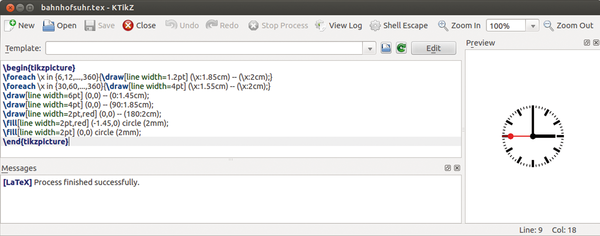 Figure 1: The KTikZ editor lets you see created graphics right away.
[...]
Buy this article as PDF
Pages: 6
(incl. VAT)
Buy Ubuntu User
US / Canada
UK / Australia
Related content
-
Fine-tuning LaTeX documents

Proofreading, wordsmithing, and finalizing the layout are all steps in the final editing phase of a document. LaTeX used with additional software can help you master these steps.
-
The RTextDoc LaTeX editor put to the test

The RTextDoc LaTeX editor promises ease of use when entering complex markup. We look at its advantages and also its shortcomings.
-
Graphviz calculates flexible graphs

Instead of toiling over a graphics layout, you can use Graphviz to concentrate on the essential content and let the software do the design.
-
Designing great tables using LaTeX

A basic LaTeX setup can only help you design simple tables. With some additional packages, however, you can jazz things up and build some nice professional-looking tables.
-
Online LaTeX Editors

You can edit your LaTeX documents with online editors that run across platforms and are device independent. Documents get saved online, thus giving you and other members of a work group easy access from anywhere.